Level Control That Decides Whether a Pumping Station Works
Level regulation is the least glamorous part of a pumping station and the part that most often brings it down. If the start and stop levels are wrong, or a switch fails to change state, the consequences are immediate: a pump that runs dry and destroys its mechanical seal, a pump that short-cycles until the motor overheats, or a wet well that overflows. The cost of the failure is never the cost of the component.
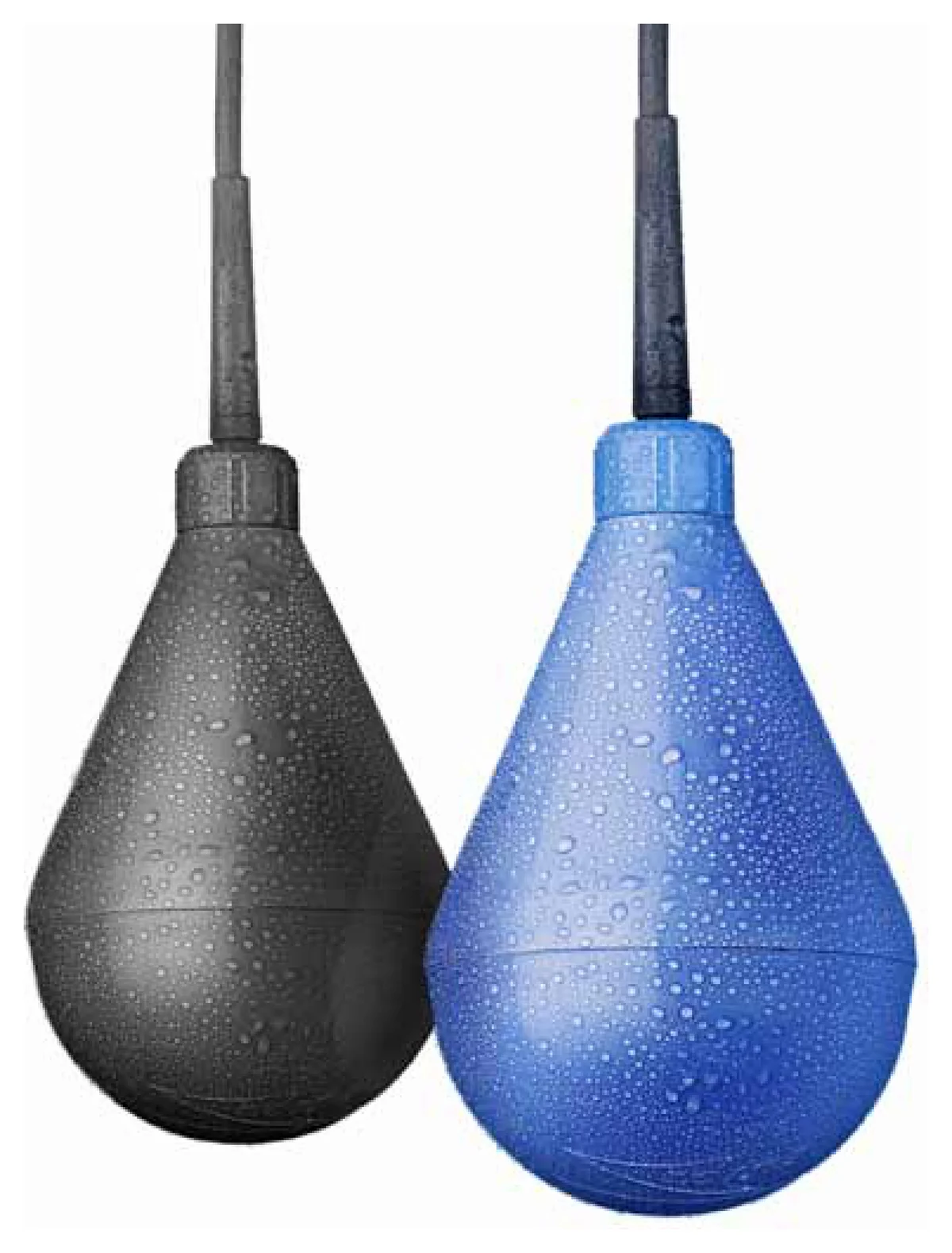
The Flygt ENM 10 — also written ENM-10 and ENM10 — is the level switch Xylem specifies for the majority of Flygt wastewater and drainage installations. It is an electromechanical tilt switch: a sealed plastic body on a flexible cable, containing a microswitch. The switch hangs freely at a defined height; when the liquid reaches it, the body tips over and the circuit makes or breaks, starting or stopping a machine or turning an alarm on or off. There is no electronics, no calibration and nothing to configure.
We supply it as a genuine Xylem part, in both the standard and the Ex-approved version, with the part numbers and cable lengths listed below. It is one of the fastest-moving items in our Flygt spare parts range, because it is a consumable on a maintenance schedule rather than a component that fails unexpectedly.
The data on this page follows Xylem's current Installation, Operation and Maintenance Manual, document 899751_16.0 (July 2022). Older brochures still in circulation give different cable availability, DC ratings and approval lists.
How the ENM 10 Works
The switch hangs on its own cable inside the wet well, clamped at the level where switching is required. As the liquid rises it lifts the body; once the body tips to the horizontal, the internal microswitch changes state. When the level falls and the body returns to vertical, the switch returns to its original state.
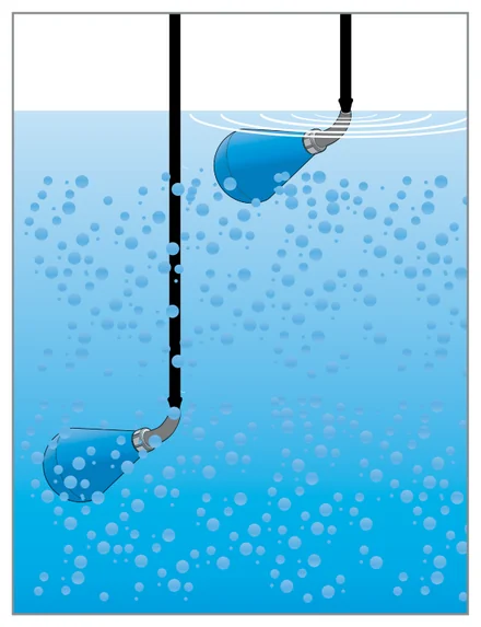
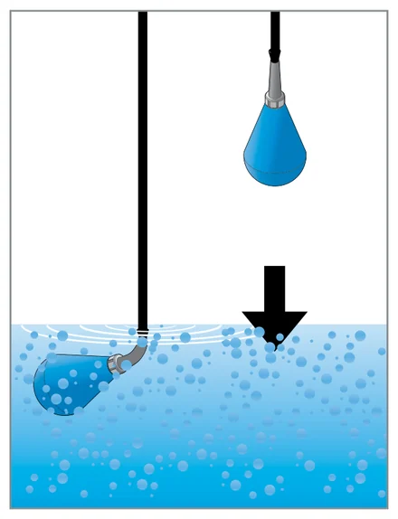
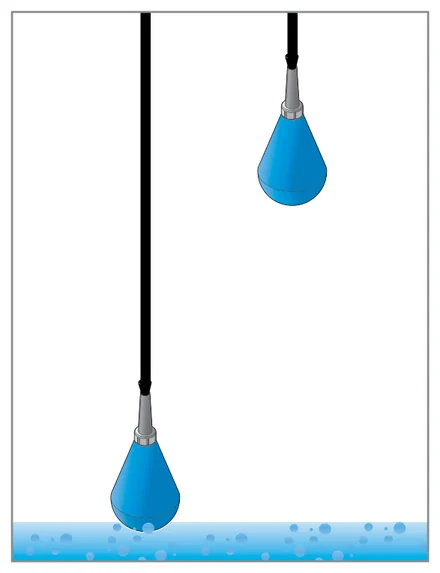
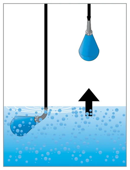
It hangs immersed, it does not float. This is the detail that separates the ENM 10 from a generic float switch. A floating switch rides on the surface and its cable drifts with the flow; where several switches share a well, the cables tangle, and a tangled cable is a switch that no longer reports the level it was set to. The manual is explicit about it: the cables must not be tangled during installation, and the cables of each switch must hang freely from each other.
Standard and Ex-Approved Versions
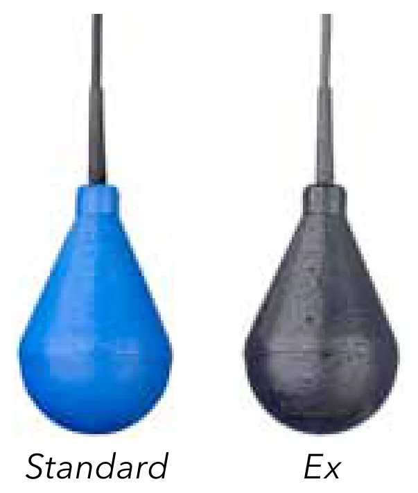
The ENM 10 is made in two versions, and they are not interchangeable.
The standard version has a blue polypropylene casing, an EPDM bend relief and a PVC cable sheath. It covers ordinary municipal and industrial duty: wastewater, stormwater, drainage and groundwater.
The Ex version has a black conductive polypropylene casing and NBR-PVC rubber throughout. The conductive casing prevents the accumulation of static charge, which is what makes it safe in a potentially explosive atmosphere. It carries ATEX, IECEx and UKEX approval, must be run in an intrinsically safe circuit with a Zener barrier, and is limited to 20 m immersion depth.
If the well can accumulate sewer gas, or the installation sits in a classified zone, the Ex version is not an upgrade — it is the only version that may legally be installed.
The Ex version is not available for the North American market.
Technical Data
| Standard version | Ex version | |
|---|---|---|
| Casing | Polypropylene, blue | Polypropylene with black conductive casing |
| Bend relief | EPDM rubber | NBR-PVC rubber |
| Cable sheath | PVC | NBR-PVC rubber |
| Cable lengths | 6, 13, 20, 30 and 50 m (20, 43, 66, 98 and 164 ft) | 6, 13, 20, 30 and 50 m (20, 43, 66, 98 and 164 ft) |
| Cable diameter | 6.7 mm (0.26 in), ± 0.2 mm | |
| Liquid density | 0.95 to 1.10 g/cm³ | |
| Liquid temperature | Up to 60 °C (140 °F) | |
| Ambient temperature | — | −20 °C ≤ Ta ≤ 60 °C |
| Immersion depth | — | Max. 20 m |
| Ingress protection | IP 68 | |
| Microswitch, AC | 250 V / 10 A resistive load 250 V / 3 A inductive load at cosφ = 0.5 | |
| Microswitch, DC | 30 V / 5 A | |
| Approvals | LVD to EN 61058 CSA certificate 1330172 | ATEX II 1G Ex ia IIC T4 Ga (NEMKO 10 ATEX 1082) IECEx ia IIC T4 Ga (IECEx NEMKO 09.0008) UKEX II 1G Ex ia IIC T4 Ga (DNV 22 UKEX 35644) |
The plastic components are welded and screwed together. Applied standards for the Ex versions are EN IEC 60079-0:2018 and EN 60079-11:2012 / IEC 60079-11:2011.
ENM 10 Part Numbers and Cable Lengths
The cable is not only a conductor — it is the mounting. The switch is clamped to a bracket or a hanging rail at the top of the well, and the length of free cable below the clamp determines both where the unit switches and how far the level has to travel between switching on and switching off. A longer free length gives a wider differential and fewer starts per hour; a shorter one gives tighter level control. The cable length is also what distinguishes one order code from the next.
| Description | Part number | Typical use |
|---|---|---|
| ENM 10 6 m (20 ft) | 5828802 | Shallow sumps, lifting stations, basement drainage |
| ENM 10 13 m (43 ft) | 5828803 | Standard municipal wet wells |
| ENM 10 20 m (66 ft) | 5828804 | Deep wet wells, stormwater tanks |
| ENM 10 30 m (98 ft) | 5828880 | Deep shafts, remote control panel |
| ENM 10 50 m (164 ft) | 5828881 | Very deep installations, long run to the panel |
The part numbers above are the standard version. The Ex version is a separate article with its own order code, available in the same five cable lengths — state the zone and we will confirm the correct number. Other cable lengths and liquid densities are available on request.
Order the cable long enough to reach the terminal box without a joint. A junction in a wet well is a failure waiting to happen, and it voids the IP 68 rating of the assembly.
Accessories and Part Numbers
Cable holder — part number 83 46 02
The dedicated clamping bracket, ø 28 mm. It holds the cable at the chosen switching level and spreads the bending load, which is where cables otherwise wear through. Worth specifying on every new installation.
Ex safety barrier — part number 84 01 07
The intrinsically active Zener barrier, mounted outside the hazardous area. It is required whenever Ex-approved ENM 10 units are installed in a classified zone — the Ex approval of the switch alone does not make the circuit intrinsically safe.
Wiring the ENM 10
The cable carries three conductors. Which two you use depends on whether the switch is emptying a sump or filling a tank — the third is insulated and left unconnected. The diagrams below show the contact arrangement with the body hanging vertically and tipped to horizontal.
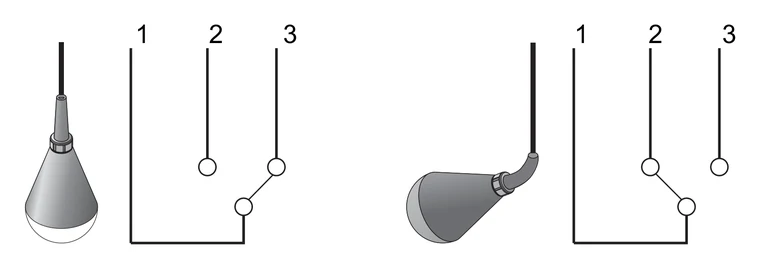
Conductor colour code
| Conductor | 1 | 2 | 3 |
|---|---|---|---|
| Colour | Grey | Black | Brown |
Pump control connections
| Conductor | To empty a sump | To fill a tank |
|---|---|---|
| 1 — grey | Connect | Connect |
| 2 — black | Connect | Insulate |
| 3 — brown | Insulate | Connect |
Alarm connections
| Conductor | High-level alarm | Low-level alarm |
|---|---|---|
| 1 — grey | Connect | Connect |
| 2 — black | Connect | Insulate |
| 3 — brown | Insulate | Connect |
Use a low-voltage control circuit. Although the microswitch is rated to 250 V, local codes in many countries require the level switch to be connected to a low-voltage supply. Xylem recommends 48 V or 24 V through a protective transformer, and the manual requires the circuit to be low-voltage via a transformer in order to meet local regulations. All electrical work must be carried out or supervised by a certified electrician, with the panel isolated and locked out first.
Approved ratings by country
The microswitch is one component, but the rating it is approved to switch is set nationally. Where your installation is governed by one of the following, the approved figures are:
| Country | Approved electrical data |
|---|---|
| Canada | 5 A, 30 V DC 10 A, 250 V AC |
| Denmark | 10 A, 250 V AC |
| Sweden | 10 A, 250 V AC resistive load 3 A, 250 V AC inductive load 5 A, 30 V DC resistive load 1 mA, 5 V DC — gold-contact version |
| Switzerland | 6 A, 250 V AC |
Switching Low Currents — the Gold-Contact Version
A standard microswitch is built to switch a real load. Wire one straight into a PLC digital input, a modern BMS card or a low-power relay drawing a couple of milliamps and you move into what is usually called dry-circuit switching, where the current is too small to break through the film that forms on a contact surface over time. The switch tests fine on the bench and then, months later, intermittently fails to report a level — which on a wet well is the expensive kind of fault, because nothing alarms.
For those circuits Xylem lists a gold-contact version of the ENM 10, rated 1 mA at 5 V DC. Gold does not form the oxide and sulphide films that defeat a silver contact at low current, so the switch stays reliable at signal-level loads. It carries its own part numbers:
| Gold-contact part numbers |
|---|
| 594 79 19 – 594 79 21 |
| 594 79 40 – 594 79 42 |
| 594 79 49 – 594 79 50 |
The exact number within these ranges depends on the cable length required. Tell us the length and the control input you are switching into and we will confirm the correct one. If you are switching a contactor coil or a conventional relay, you do not need the gold-contact version — the standard part is the right choice and the cheaper one.
Ex installations
Intrinsically safe circuits are normally required — Ex i. The ENM 10 must be run through the Zener barrier, part number 84 01 07, which sits outside the hazardous area. The relevant intrinsic safety figures:
| Parameter | Value |
|---|---|
| Maximum input voltage, Ui | 30 V |
| Maximum input current, Ii | 100 mA |
| Maximum input power, Pi | 1.2 W |
| Maximum internal capacitance, Ci | 4.0 nF |
| Maximum internal inductance, Li | 29.0 µH |
| Barrier supply voltage (84 01 07) | 120–230 V, 48–62 Hz |
| Barrier output voltage, Uo | 8.2 V |
| Barrier permissible external capacitance, Co | 16.2 µF |
| Barrier permissible external inductance, Lo | 230 mH |
| Barrier input resistance, R | 1000 Ω |
Electrical connections must comply with the Ex regulations of the national submitter.
How Many Level Switches Does a Station Need?
The manual sets a floor: two switches must be used — one for start and one for stop. Where an alarm is required at a given level, a third switch is connected for it. The same part can be used for all three functions; nothing distinguishes a start switch from a stop switch except where it is clamped and how it is wired.
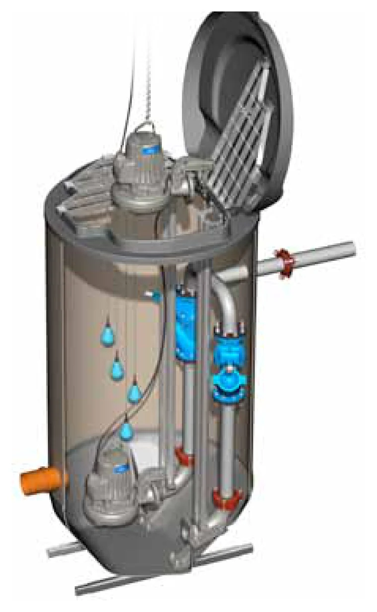
In a two-pump station, four switches are generally used: one at the stop level, one at each pump's start level, and a fourth for the high-level alarm. Staggering the two start levels is what gives duty/standby alternation and prevents both pumps from starting into the same inflow.
Because the units are consumables operating in sewage, most maintenance schedules replace all switches in a well at the same time rather than one at a time. Replacing one and leaving three of the same age in place usually means a second call-out within the year.
The same logic applies to the packaged units in our sewage lifting stations range, where level control is built into the tank.
Where the ENM 10 Is Used
Municipal wastewater
Wet wells and pumping stations on the public sewer network — the ENM 10's original and largest application.
Stormwater and rainwater
Retention tanks and surface water pumping, where the level often moves slowly and a switch must act reliably at low speed.
Drainage and groundwater
Dewatering sumps, land drainage and groundwater control, including construction and civil works.
Building drainage
Basement and below-sewer-level drainage, in packaged lifting units and purpose-built pits alike.
Industrial process sumps
Collection pits in processing plants, subject to the density and temperature limits in the table above.
Alarm duty
High- or low-level alarm in any of the above — the same switch wired to an alarm rather than a starter.
Maintenance
Maintenance is inspection, not repair. Clean fat and grease off the plastic surface, then inspect the cable, the protective sleeves and the plastic casing for damage. If the switch is damaged it must be replaced — it is hermetically encapsulated and cannot be repaired. On Ex installations, verify that the barrier is working by checking that its LED changes when the switch is toggled.
No lead, no mercury, no adhesives. The ENM 10 contains none of the heavy metals found in older tilt switches, and its plastic components are welded and screwed rather than glued — which is also why it tolerates the aggressive liquids that dissolve bonded assemblies. If you are replacing legacy mercury tilt switches, the ENM 10 is the direct functional equivalent without the disposal obligations. At end of life, dispose of it as waste electrical and electronic equipment under WEEE (EU Directive 2012/19/EU, UK SI 2013 No. 3113), not with general waste.
Genuine or Nothing
Level switches attract copies, because the shape is simple and the price point is low. What the copies do not reproduce is the microswitch, the cable compound and the weld integrity of the casing — and those are precisely the three things that determine whether the unit is still switching after three years in sewage. A failed switch does not announce itself; it simply stops reporting, and the first sign is a dry-run or an overflow. Xylem's own manual puts it plainly: only original spare parts should be used, and unsuitable parts may cause malfunction, damage and injury as well as voiding the warranty.
Everything we supply is genuine Xylem product with documented origin. See why genuine parts matter, and our Flygt 3127 parts page for the pumps these switches most often control.
What to Specify When Ordering
Version
Standard or Ex. If the installation is in a classified zone, state the zone and the required equipment category.
Cable length
6, 13, 20, 30 or 50 m. Measure from the clamping point to the terminal box, not from the liquid surface.
Quantity and function
How many units, and what each one does — start, stop, alarm. This lets us check the count against the station type before we quote.
The media
What is being pumped, its approximate density and its temperature. Densities outside 0.95–1.10 g/cm³ and temperatures above 60 °C need a different specification.
Accessories
Cable holders (83 46 02), and the Ex safety barrier (84 01 07) where the Ex version is used.
Frequently Asked Questions
What is the Flygt ENM 10 used for?
The Flygt ENM 10 is an electromechanical level switch - a tilt switch used to start and stop pumps and to turn alarms on and off in wastewater, stormwater, drainage and groundwater installations. It is installed freely hung at a defined height; when the liquid level reaches it, the body tips over and the circuit makes or breaks.
What is the part number for the Flygt ENM 10?
The standard version carries a different part number for each cable length: 5828802 for 6 m, 5828803 for 13 m, 5828804 for 20 m, 5828880 for 30 m and 5828881 for 50 m. The Ex version is a separate article with its own order code. The cable holder is 83 46 02 and the Ex safety barrier is 84 01 07.
What are the ENM 10 wire colours and how do I connect it?
The cable has three conductors: 1 is grey, 2 is black, 3 is brown. To empty a sump, connect conductors 1 and 2 and insulate 3. To fill a tank, connect conductors 1 and 3 and insulate 2. The same applies to alarm duty: conductors 1 and 2 for a high-level alarm, conductors 1 and 3 for a low-level alarm, insulating the unused conductor in each case.
What cable lengths are available for the ENM 10?
Both the standard and the Ex version are available with 6, 13, 20, 30 or 50 m of cable (20, 43, 66, 98 or 164 ft). The cable diameter is 6.7 mm for all variants, plus or minus 0.2 mm. Other cable lengths are available on request. Note that older brochures list the Ex version with shorter lengths only; the current manual lists all five for both versions.
What is the difference between the standard and the Ex version?
The standard version has a blue polypropylene casing, an EPDM bend relief and a PVC cable sheath, for ordinary wastewater and drainage duty. The Ex version has a black conductive polypropylene casing and NBR-PVC rubber throughout, which prevents static charge accumulation, and carries ATEX, IECEx and UKEX approval for use in potentially explosive atmospheres. The Ex version must be run in an intrinsically safe circuit through a Zener barrier, is limited to 20 m immersion depth, and is not available for the North American market.
Does the Flygt ENM 10 contain mercury?
No. The ENM 10 contains no mercury and no lead, and no adhesives are used in its construction - the plastic components are welded and screwed together. It is a direct functional replacement for legacy mercury tilt switches, without their disposal obligations.
What liquid densities and temperatures can the ENM 10 handle?
The cable lengths listed are specified for liquids with a specific density between 0.95 and 1.10 g/cm3. The switch withstands liquid temperatures up to 60 degrees Celsius (140 degrees Fahrenheit). Versions for other liquid densities are available. The Ex version has an ambient temperature rating of minus 20 to plus 60 degrees Celsius.
What are the electrical ratings of the microswitch?
The microswitch is rated at a maximum of 250 V AC / 10 A. The interrupting capacity is 250 V AC at 10 A for a resistive load, 250 V AC at 3 A for an inductive load at a power factor of 0.5, and 30 V DC at 5 A. Approved ratings vary by country, and local codes often require a lower voltage than the switch is approved for.
Should the ENM 10 be connected to mains voltage?
In most cases no. Local codes in many countries require the level switch to be connected to a low-voltage supply even though it is approved for a higher voltage. Xylem recommends 48 V or 24 V through a protective transformer. All electrical work must be carried out or supervised by a certified electrician, with the unit and the control panel isolated and locked out beforehand.
How many level switches does a pumping station need?
At least two - one for start and one for stop - with a third added where an alarm is required at a given level. The identical switch can be used for all functions. A two-pump station generally uses four: one at the stop level, one at each pump's start level, and a fourth for the high-level alarm.
Do I need a safety barrier with the ENM 10?
Yes, in any Ex installation. Intrinsically safe circuits are normally required, and the Flygt Ex safety barrier, part number 84 01 07, must be installed outside the hazardous area. The Ex approval of the switch by itself does not make the circuit intrinsically safe - the barrier is part of the approved arrangement.
Can the ENM 10 switch a PLC input or another low-current circuit?
Not the standard version, reliably. A standard microswitch is built to switch a real load, and at signal-level currents a contact film can build up that the current is too weak to break through - the switch then fails intermittently, often months after commissioning. For PLC inputs and similar low-current circuits, Xylem lists a gold-contact version of the ENM 10 rated 1 mA at 5 V DC, under part numbers 594 79 19 to 594 79 21, 594 79 40 to 594 79 42, and 594 79 49 to 594 79 50. If you are switching a contactor coil or a conventional relay, the standard part is the correct and cheaper choice.
Can a damaged ENM 10 be repaired?
No. The unit is hermetically encapsulated and cannot be opened or repaired. If inspection shows damage to the cable, the protective sleeves or the plastic casing, the switch must be replaced. Routine maintenance is limited to cleaning fat and grease off the plastic surface and visual inspection.
Can the ENM 10 replace another brand of float switch?
In most cases yes, provided the electrical rating, the cable length and the liquid density are compatible, and provided the mounting arrangement allows the unit to hang freely rather than float. Send us the make and model you are replacing along with the station details and we will confirm before you order.