The Flygt ENM 10 is the simplest component in a pumping station and it still gets wired wrong. Three conductors come out of the cable; you use two and insulate the third, and which two depends on what the switch is doing. Get it backwards and the pump starts when the well is empty. This article sets out the colour code, the two connection cases, alarm wiring, the voltage rule, what changes in an Ex installation, and the faults we see that look like wiring errors but are something else.
Everything below follows Xylem's current Installation, Operation and Maintenance Manual for the ENM 10, document 899751_16.0. Where we add field practice, we say so.
What you are connecting
Inside the sealed body is a single microswitch with a changeover contact, operated by the tilt of the body. The cable carries three conductors:
| Conductor | Colour | Role |
|---|---|---|
| 1 | Grey | Common — connected in every configuration |
| 2 | Black | Used when the switch must act on a rising level |
| 3 | Brown | Used when the switch must act on a falling level |
The grey conductor is always in circuit. The choice is between black and brown, and the one not used must be insulated — properly, with a heat-shrink or an insulated crimp, not taped and tucked.
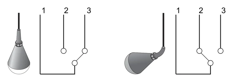
Emptying a sump or filling a tank
This is the decision that matters. A switch controlling a drainage pump must start the pump when the level rises; a switch controlling a filling pump must start it when the level falls. Same component, opposite conductors:
| Conductor | To empty a sump | To fill a tank |
|---|---|---|
| 1 — grey | Connect | Connect |
| 2 — black | Connect | Insulate |
| 3 — brown | Insulate | Connect |
Almost every Flygt wastewater installation is the first case. If you are replacing a switch in a wet well and find brown connected, somebody before you either wired it for a tank or made the mistake this article exists to prevent. Check before copying.
Start and stop with two switches
A single ENM 10 cannot run a pump on its own, because the level at which it tips and the level at which it falls back are a few centimetres apart — the pump would cycle constantly. The manual requires two switches as a minimum: one clamped at the start level, one at the stop level, with a third added wherever an alarm is needed. The same part serves every position; nothing distinguishes a start switch from a stop switch except where it hangs and how the panel uses it.
In the control circuit, the upper switch closes on a rising level and energises the pump contactor through a relay that holds itself in; the lower switch, which closed earlier as the level passed it, opens again when the level falls below it and drops the circuit out. The pump therefore runs from the moment the upper switch tips until the moment the lower switch hangs vertical again. The distance between the two clamping points is your operating band — wider means fewer starts per hour, narrower means tighter level control.
In a two-pump station the usual arrangement is four switches: a common stop, a start for each pump at staggered heights, and a high-level alarm above them all. Staggering the two starts is what gives you duty/standby and prevents both pumps from starting into the same inflow.
Alarm wiring
An alarm switch follows the same logic as a pump switch, and the same table:
| Conductor | High-level alarm | Low-level alarm |
|---|---|---|
| 1 — grey | Connect | Connect |
| 2 — black | Connect | Insulate |
| 3 — brown | Insulate | Connect |
The high-level alarm is the one that earns its keep. It is the only thing that tells anyone the start switch has failed before the well overflows. Hang it above the highest start level with enough margin that normal surges do not trip it, and wire it to something that is actually monitored.
The microswitch is rated to 250 V AC / 10 A, and people read that as permission to switch the contactor coil directly from mains. In most countries the local code says otherwise: the level switch circuit must be low-voltage, fed through a transformer. Xylem's recommendation is 24 V or 48 V through a protective transformer. Apart from compliance, a low-voltage circuit is safer for whoever next puts their hands in the well, and it is kinder to the contacts. All of this work must be done or supervised by a certified electrician, with the panel isolated and locked out first — the control circuit included.
Low-current circuits and PLC inputs
There is one case where the standard switch is the wrong part even though it works on the day. A PLC digital input or a modern building-management card draws a few milliamps. That is dry-circuit switching, and a standard contact can develop a surface film over months that such a small current cannot break through. The symptom is an intermittent fault that appears long after commissioning. For those circuits Xylem lists a gold-contact version of the ENM 10, rated 1 mA at 5 V DC, under separate part numbers. If you are switching a relay or a contactor coil, you do not need it.
Ex installations
In a classified zone the rules change in three ways. First, the switch itself must be the black Ex version, not the blue standard one — the conductive casing is what prevents static build-up. Second, the circuit must be intrinsically safe, which means the Flygt Ex safety barrier, part number 84 01 07, installed outside the hazardous area; the Ex approval of the switch alone does not make the circuit safe. Third, the Ex switch is limited to 20 m immersion depth regardless of cable length. The barrier has an LED that changes state when the switch toggles — the manual's own commissioning check is to watch it do so.
Do not mix a standard switch into an Ex circuit “just for the alarm”. Every switch in the hazardous area is Ex, or none of the approval holds.
Faults that look like wiring errors and are not
Field practice, not the manual. Most call-outs for “the float switch is wired wrong” turn out to be one of these:
| Symptom | Likely cause | Check |
|---|---|---|
| Pump never starts | Start switch wired for a tank (1 + 3), or cannot tip because it is tangled with another cable or snagged on the guide rail | Continuity across 1 and 2 with the body tipped by hand; look at the cables |
| Pump never stops | Stop switch held tipped by the pump discharge or a bracket; or a contact welded after switching a load above its rating | Lift the switch; continuity with the body vertical |
| Pump short-cycles | Start and stop clamped too close together; or a non-return valve passing and refilling the well from the main | Measure the operating band; watch the level after a stop |
| Works for months, then intermittent | Standard contact on a low-current input (see above); or a joint in the cable inside the well | Replace with the gold-contact version; never joint a cable in a wet well |
| Alarm never trips, or is always on | 2 and 3 swapped | Compare against the table above |
| Switch slow or sticks near horizontal | Fat and grease on the body | Clean the plastic surface — the manual lists this as routine maintenance |
Mounting mistakes that cause electrical symptoms
The manual is short and specific on mounting: the cables must not be tangled during installation, and each switch's cable must hang freely from the others. The ENM 10 hangs immersed from a fixed clamping point rather than floating on the surface precisely so that several of them can share a well without fouling. Use the dedicated cable holder, part number 83 46 02, at the clamping point; it is where cables otherwise wear through. Order the cable long enough to reach the terminal box in one run — a junction inside the well is both a future fault and the end of the IP 68 rating. Standard cable lengths are 6, 13, 20, 30 and 50 m, each under its own part number.
When to replace rather than diagnose
The ENM 10 is hermetically encapsulated and cannot be opened or repaired. If the cable, the protective sleeve or the casing shows damage, the manual's instruction is to replace the switch. Because the units in a well are the same age and have seen the same duty, most maintenance schedules replace them as a set rather than one at a time; replacing one and leaving three equally old ones in place usually means another visit within the year. A set of switches is the cheapest line on any pumping-station spares list, and the one whose failure costs the most — see our note on what a pump failure actually costs.
Key takeaways
- Grey is always connected. Black for a rising level (empty a sump, high-level alarm), brown for a falling level (fill a tank, low-level alarm). Insulate the third.
- Two switches minimum — start and stop. Four in a two-pump station. A high-level alarm wherever an overflow would matter.
- Low-voltage control circuit, 24 V or 48 V through a transformer, whatever the contact rating says.
- PLC input? Gold-contact version. Classified zone? Ex version plus barrier 84 01 07, barrier outside the zone.
- Cables hang freely from a fixed clamp, no joints in the well, clean off the grease. Replace, don't repair, and replace as a set.
Frequently asked questions
What are the wire colours on a Flygt ENM 10?
Conductor 1 is grey, conductor 2 is black and conductor 3 is brown. Grey is the common and is connected in every configuration; black or brown is connected depending on the duty, and the unused one is insulated.
Which wires do I connect to make the pump empty a sump?
Connect grey (1) and black (2) and insulate brown (3). The switch then closes on a rising level, which is what a drainage or wastewater pump needs. To fill a tank it is the reverse: grey and brown connected, black insulated.
How do I wire an ENM 10 as a high-level alarm?
Exactly as for emptying a sump: grey and black connected, brown insulated. For a low-level alarm, grey and brown connected, black insulated. Hang the high-level alarm switch above the highest pump start level with enough margin that normal surges do not trip it.
Can I connect the ENM 10 directly to 230 V?
The microswitch is rated to 250 V AC / 10 A, but local codes in most countries require the level switch circuit to be low-voltage, fed through a transformer. Xylem recommends 24 V or 48 V through a protective transformer. Treat the 250 V rating as a limit, not a design value.
Why does my ENM 10 work for months and then become intermittent?
Two common causes. If the switch is on a low-current circuit such as a PLC input, a standard contact can develop a surface film that a few milliamps cannot break through - the gold-contact version of the ENM 10 exists for that case. Otherwise, look for a cable joint inside the well, which will corrode no matter how well it was made.
Do I need a safety barrier?
In any classified zone, yes. The Ex version of the ENM 10 must be run through the Flygt Ex safety barrier, part number 84 01 07, installed outside the hazardous area. The switch's own Ex approval does not make the circuit intrinsically safe on its own.